175 Results
View results:
Sort by:
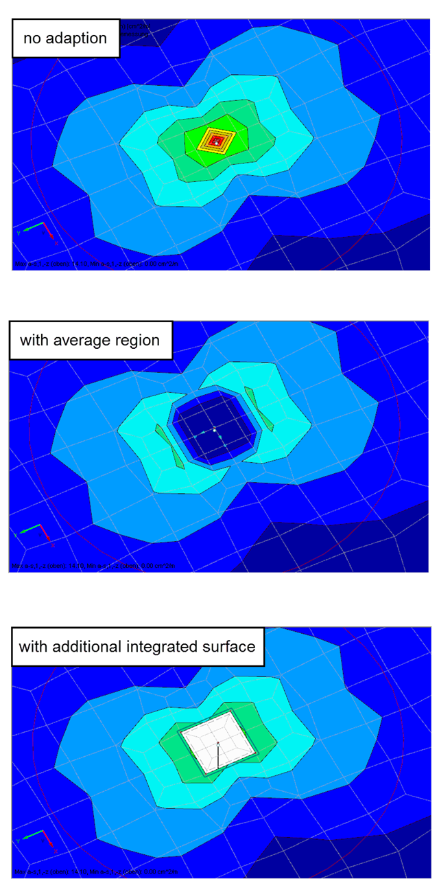
Singularities occur in a limited area due to the concentration of the stress-dependent result values. They are conditioned by the FEA methodology. In theory, the stiffness and/or the stress in an infinite size concentrate on an infinitesimally small area.
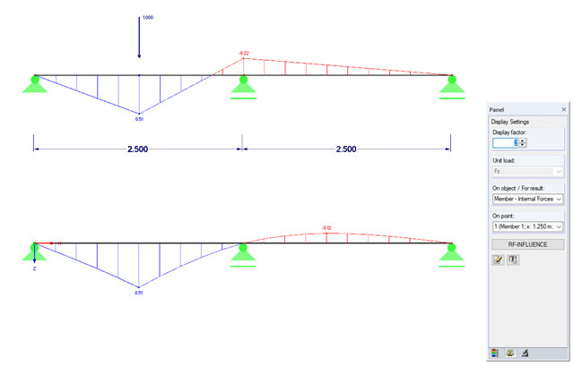
Influence lines are less important nowadays due to fast computer systems. However, it might be an advantage to use influence lines in the phase of preliminary design, as well as in the actual creation of the structural designs. With the RF-INFLUENCE add-on module, influence lines and influence surfaces can be generated and evaluated easily due to a fixed internal force. This technical article describes, with a simple example, the basics of determining and evaluating influence lines.
![Parameters of Effective Slab Width (Figure 5.3 [1])](/en/webimage/009561/2419376/01-en-png.png?mw=640&hash=c76563b459152b19c98197ea6ba342be89d9a5bc)
In the case of combined FEM structures (surface and member elements) as well as folded plate structures, it is possible to attribute a beam structure for the design on a member to a fictitious T-beam cross-section, whose geometry depends on the effective width. When using the "Rib" member type in RFEM, the stiffness is represented by a slab component (surface element) and a web component (member element). This approach has some design specifics that are explained in this article.

In accordance with Sec. 6.6.3.1.1 and Sec. 10.14.1.2 of ACI 318-14 and CSA A23.3-14, respectively, RFEM effectively takes into consideration concrete member and surface stiffness reduction for various element types. Available selection types include cracked and uncracked walls, flat plates and slabs, beams, and columns. The multiplier factors available within the program are taken directly from Table 6.6.3.1.1(a) and Table 10.14.1.2.
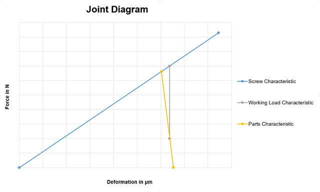
When modeling surface models, such as a frame joint or similar structures, there is always the question of how to model a prestressed bolt connection. In this case, it is always necessary to find a compromise between the practicable and detailed solution. The following article describes the modeling procedure of such a connection, based on the joint diagram calculation method.
When analyzing structural components of reinforced concrete structures, it is often necessary to design deep beams. These are mainly used for window and door lintels, upstand and downstand beams, the connection between split-level slabs, and frame systems. If they are displayed as surfaces in RFEM, the evaluation of reinforcement results requires further steps.
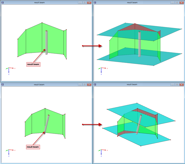
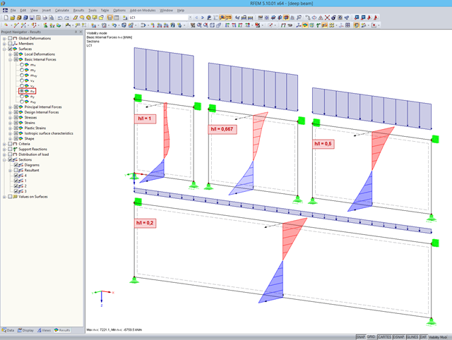
The "Result Beam" member type has been available since the release of RFEM 5. The result beam is a virtual member that does not have any stiffness nor require any support. It can be used in various situations in order to integrate the results from members, surfaces, and solids, and to display them as member internal forces.

The calculation of timber panels is carried out on simplified member or surface structures. This article describes how to determine the required stiffness.
Buildings are structures surrounded by wind. The flow around them creates specific loads on the surfaces, which are to be used for the design in structural analysis.

Wind blowing parallel to the surfaces of a structure can generate friction forces on these surfaces. This effect is important mainly for very large structures.
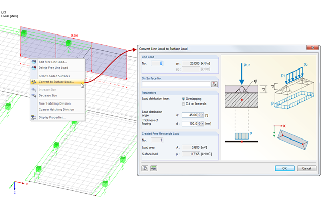
When modeling a load in RFEM, line loads on surfaces are used very often. This may be a line load directly related to a particular load, or a free line load entered at the start and end coordinates.
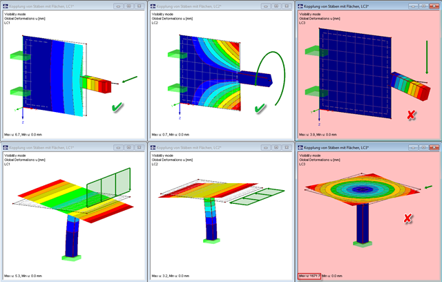
Pay particular attention to the connection points of members and surfaces when you deal with mixed systems, because not all internal forces can always be transferred without difficulty at the coupling location.

This article describes how a flat slab is generated as a 2D model in RFEM and the loading is applied according to Eurocode 1. The load cases are combined according to Eurocode 0 and calculated linearly. In the RF-CONCRETE Surfaces add-on module, the bending design of the slab is performed while taking into account the standard requirements of Eurocode 2. The reinforcement is complemented by a rebar reinforcement for areas that are not covered by the mesh basic reinforcement.

Reinforced concrete surface design for slabs, plates, and walls is possible in the RF-CONCRETE Surfaces module according to the ACI 318-19 or the CSA A23.3-19 standard. A common approach for slab design is the use of design strips for determining the average one-way internal forces over the width of the strip. This design strip method essentially takes a two-way slab element and applies a simpler one-way approach to determine the required reinforcement needed along the strip length.

In SHAPE-THIN, the calculation of stiffened buckling panels can be performed according to Section 4.5 of EN 1993-1-5. For stiffened buckling panels, the effective surfaces due to local buckling of the single panels in the plate and in the stiffeners, as well as the effective surfaces from the entire panel buckling of the stiffened entire panel, have to be considered.

In RF-STEEL Surfaces, it is possible to display the stresses relevant for the design of welds, for example, according to EN 1993‑1‑8, Figure 4.5. When evaluating the stress components, the local xyz-axis system of the surfaces must be considered.
![Structural System and Cross-Section Dimensions According to [1]](/en/webimage/009153/2417271/01-en-png.png?mw=640&hash=c76563b459152b19c98197ea6ba342be89d9a5bc)
There are several options for calculating a semi-rigid composite beam. They differ primarily in the type of modeling. Whereas the Gamma method ensures simple modeling, additional efforts are required when using other methods (for example, shear analogy) for the modeling which are, however, offset by the much more flexible application compared to the Gamma method.
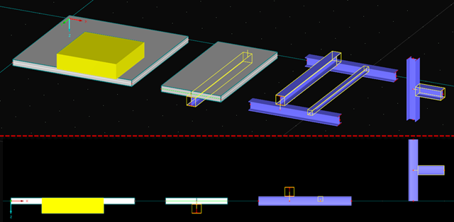
In the case of a parallel offset of the structural plane of members and surfaces and also applying an axial offset to members, for example, the function of eccentricities may be useful.
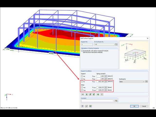
A previous article presented different variants of surface elastic foundations in addition to the traditional subgrade reaction modulus method. The following article describes another method for surface foundation. This method considers the adjacent ground areas by means of a foundation overlap. In this case, foundation parameters refer to the continuing works by Pasternak and Barwaschow.

The RF‑/STEEL EC3 add-on module can perform the design of fillet welds for all parametric, welded cross-sections of the cross-section library. For this, the option must be activated in the detail settings of the module. As an alternative, you can also use a surface model for the design.